General Description
1. Decription
A. General
The IR-Opflow is an axial paddle wheel turbine type flow meter based on the Pelton wheel principle. This unique patented design makes the IR-Opflow a very accurate, repeatable, linear device. Not only is the IR-Opflow precise, but it is also a rugged, trouble-free flow meter, which can be used in a wide variety of industries including: medical, pharmaceutical, chemical processing, pulp & paper, semi-conductor, biotech, agriculture etc.
B. Principle of operation
Fluid flows through the meter, first passing through a helical nozzle, which causes flow to spiral, rotating in a helical pattern. The spiraling fluid then impacts on the flat blade rotor causing the rotor to spin. The rotor is designed to immediately develop a rotation-induced friction-free fluid bearing, thus eliminating any potential bearing wear.
An infrared electro-optical transmitter and receiver is molded into the body of the meter along with a pair of miniature circuit boards, providing voltage stabilizers.*
This design inherently bleeds off entrained gas, improving the accuracy of the meter. It also eliminates the need for flow straighteners or special lengths of inlet piping to stabilize turbulent flow.
* Clear, transparent & translucent fluids; must transmit infrared light.

2. Material Characteristics
A. Material of construction
Chemical name – Polyvinylidene Fluoride
Trade name – Solef
All wetted parts of the IR-Opflow are PVDF, excluding the O-ring. Wetted parts include any part of the meter that will or could come in contact with the fluid.
List of wetted parts:
1. Barbed fittings
2. End caps
3. Flow meter body
4. Strainer
5. Rotor
6. Bearings
7. Helical nozzle (Viton O-ring seal)
B. Chemical Composition
Polyvinylidene Fluoride is a fluorpolymer consisting of three basic materials (carbon, hydrogen and fluorine)
C. Chemical Compatibility
For a complete list of compatible fluids contact JLC International
D. Effects of Various Fluids
· Weak acids – no effects
· Strong acids – attacked by fuming sulfuric & nitric acids at high temperature
· Weak alkalis – no effects
· Strong alkalis – no effects
· Organic solvents – Resistant to most. Slight attack by some. Imbrittled by some amines, ketone and esters. (Reference Compass Corrosion Guide II)
Parameters
3. Operating Parameters
A. Temperature
Since the IR-Opflow has printed circuit boards molded into the body of the meter it is strongly recommended that 85 °C (185 °F) not be exceeded. Exceeding 85 °C (185 °F) can cause irreparable damage to the circuit boards.
B. Flow ranges
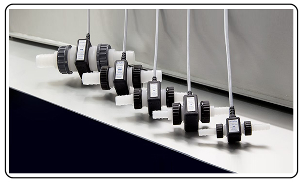
The IR-Opflow is available in six different sizes, which cover a flow range from 0.1 – 120 lpm.
Specific flow ranges
Type 1 0.1 – 2 lpm (0.03-0.53 gpm)
Type 2 0.3 – 9 lpm (0.08-2.38 gpm)
Type 3 0.5 – 15 lpm (0.13-3.96 gpm)
Type 4 1.0 – 30 lpm (0.26-7.93 gpm)
Type 5 2.5 – 75 lpm (0.66-19.8 gpm)
Type 6 4.0 – 120 lpm (1.32-32 gpm)
Consult factory with specific applications requiring an extended flow range. Warning: Over range may permanently damage the flow meter.
C. Recommended viscosity
Range 1-5 cSt (w/o correction)
The effects of changing viscosity on the IR-Opflow are the same as any other turbine flow meter. It is important to remember that a turbine meter is a viscosity dependent device, where as the viscosity increases the linearity of the flow meter will decrease. (Water like viscosities are ideally suited for use with the IR-Opflow) The IR-Opflow is factory calibrated with water.
Correction procedure for higher viscosity
For viscosities greater than 5 cSt consult the factory. The IR-Opflow can be used on fluids greater than 5 cSt. however, the K-factor (linearity) will change. This requires a recalibration of the IR-Opflow at the known viscosity to determine the new K-Factor.
D. Filter Recommendations
| Meter | Micron | Mesh |
| Type1 | 35 | 400 |
| Type2 | 50 | 300 |
| Type3 | 100 | 80 |
| Type4 | 100 | 80 |
| Type5 | 100 | 80 |
| Type6 | 100 | 80 |
IR-Opflow sizes 2 – 6 are fitted with strainers* to help protect against dirt, fiber and other contaminants. Due to space restrictions it is not possible to fit size 1 with a strainer. Removal of the strainer will reduce pressure drop through the flow meter and may also change the linearity of the meter to solid contaminant, which could damage the meter.
* The strainer is a 30 mesh filter / 550 micrometer. Cartridge models have no strainer.
E. Cleaning
1. Steam cleaning
Steam sterilization is not possible with IR-Opflow due to the high temperature of the steam. Steam sterilization will permanently damage the flow meter bearings and printed circuit boards.
2. Chemical cleaning
Chemical cleaning the IR-Opflow is permissible, provided the chemicals are compatible with PVDF (polyvinylidene fluoride).
F. Bi-directional flow
The IR-Opflow is designed to only provide fluid readings in the forward flow direction. Reverse flow will not unduly restrict fluid flow.
4. Silicone Treatment
Silicone treatment is standard for all types of the IR-Opflow series electronics.
Infrared Sensors
5. Infrared Sensor
A. Supply voltage
5-12 Vdc / 8 – 24 Vdc. Do not exceed 12 Vdc / 24 Vdc. Doing so can cause overheating and eventual failure of all PC boards. Printed circuit boards are non-repairable.
B. Frequency output
- Square wave pulse, unscaled
- Output impedance 75 ohms
- Directly proportional to flow rate
- Output – dc frequency
- Offset 0.64 volts
- Peak voltage = Supply voltage – 1.2 volts
- Peak to peak voltage = Supply voltage – 1.2 volts – 0.64 volts
- Output signal cycle 66.7% (i.e. at 100Hz there is a 6 millisecond “on” time and a 4 millisecond “off” time)
- TTL/CMOS circuit compatibility. The IR-Opflow has an operational amplifier output, which has high input impedance and low output impedance.
C. Frequency Ranges for
| (non-cartridge models) | pulses/I | |
| Model | Frequency (Hz) | K-Factor |
| Type1 | 60-1200 | 36,000 |
| Type2 | 40-1200 | 8,000 |
| Type3 | 27-800 | 3,200 |
| Type4 | 20-600 | 1,200 |
| Type5 | 18.75-562 | 450 |
| Type6 | 15-450 | 225 |
D. Cable requirements1. 20 – 22 AWG2. 4 conductor-shielded cableNote: Avoid influences of strong electromagnetic forces as they can damage components on the PC boards.
6. Installing IR-Opflow
A. Make sure the fluid is compatible with PVDF (polyvinylidene fluoride) and meets viscosity, pressure and temperature parameters of the IR-Opflow. The fluid must also meet filtration requirements as listed in 3D.
B. Install the IR-Opflow in the fluid line with the arrow pointing in the direction of the flow.
C. While installing the IR-Opflow in the fluid line be careful not to over-torque the end caps (on hose-barbed flowmeters) or other fittings on the flowmeter. Due to the relatively soft composition of PVDF the body or threads can be permanently distorted.
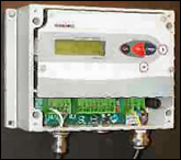
D. Attach wires to the readout display with the display and power off. Not only will this help to avoid a potential shock hazard, but it can also help prevent an error in hooking the flow meter to an incorrect 115 Vac supply.
E. Connect digital display to power supply and enter scaling factors for both the rate and total. Follow the manufacturers instructions for programming the digital display.
F. The IR-Opflow is now ready for use.
Supply & Output
| Supply Voltage and Signal Output Connections | Note:Use ‘black’ to pull down ‘green’ to zero if necessary by connecting to ground. |
 |
JLC International, Inc. warrants to the original purchaser, for the period of one year from the date of purchase, that each flow meter is free from defects in materials and workmanship.
The warranty does not cover meters that have been damaged due to abuse, incorrect installation and operated beyond JLC’s stated maximum parameters of the IR-Opflow. JLC’s sole obligations under the warranty are limited to the repair or replacement of parts, determined to be defective after inspection by JLC. Repair or replacement of parts at JLC’s discretion.
JLC is not liable for any consequential damages or any contingent liabilities arising out of the failure of any flow meter part, component part or accessory.
The above warranty supersedes and is lieu of all other warranties, either expressed or implied and all other obligations or liabilities. No agent, representative or distributor has any authority to alter the terms of this warranty, in any way.
| Series x00.x0x: 5 – 12 Vdc | Series x00.x1x 8 – 24 Vdc |